|
Functionalities and Application
¤ Electrical conversion between G.703 and V.35 ports
¤ It can realize framing from G.703 to V.35 and has five kinds of communication modes of PCM31, PCM31C, PCM30 and PCM30C. Besides, it allows random withdrawing of time slots to compose N*64K (N=1~32) data channels.
¤ To facilitate utilization in various circumstances, the converter is endowed with four kinds of different loop-back (including loop-back of local terminal and remote terminal of V.35 and loop-back of local terminal and remote terminal of E1).
¤ Pseudo-random code can be generated to test conditions of circuitries and equipments.
¤ Network management function, to control every configuration of the converter and monitor the working status of the converter through network line
¤ Hyper terminal function, to configure and monitor the working status of the converter through the hyper terminal port.
¤ Support dual power, DC-48V,AC220V are available simultaneity.
Parameters and Indices
Criterion of 2M port: Full accordance with ITU-T G.703 Recommendations
Code pattern: HDB3
Code rate: 2.048Mb/s±50ppm
Type of E1 port: Unbalanced 75Ω/BNC
Balanced 120Ω/RJ45
Criterion of V.35 port:
Code rate: 2.048Mb/s,N*64Kb/s
Clock: Internal clock is slave clock, and external clock is optional. For the phase relationship of sending data and sending clock and the relationship of receiving data and receiving clock of V.35, the positive edge and negative edge are optional.
Mode of interfacing: V.35 / DCE
Electrical characters: Full accordance with ITU-T V.35 Recommendations
Standard of terminals: In accordance with ISO2593 specifications
Dimensions 200mm×150mm×40mm
Service Conditions
Inputting voltage AC 185 ~ 265V 50/60 Hz
DC –48V ± 20%
Power consumption < 5W
Operating temperature 0℃ ~ 40℃
Storage temperature –25℃ ~ +55℃
Relative humidity 5% ~ 95% (35℃)
No corrosive and solvent gas, no fluty dust and intense magnetic-field interference.
SYSTEM PARAMETER:
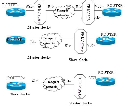
1. TIMING MODE INT OSC (default): Mater clock. The equipment uses clock generated by internal oscillate at the time.
EXT CLK: External clock. The equipment receives clock from V.35 port. The clock mode is usually used in end-to-end joint with DCE equipments and is called DCE-to-DCE mode.
RECOVERY: Slave clock. Working clock of the equipment withdraws slave clock from the received E1 signals. Equipments working in the mode are capable of tracking the remote terminal automatically.
Typical operation modes:
Note:
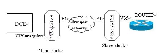
Line clock should not be applied on all the equipments. If you are sure that there is already equipment providing clock in the circuit, then the other equipments can be set as line clocks. If you are not clear whether there is equipment providing clock in the circuit, equipments should be set as internal clocks.
If end-to-end joint of V.35 port with DCE equipment (such as V.35 port of DDN, ATM, HDSL and MODEM of base band) is required, cross spider should be used. If V.35 port of the remote DCE equipment is set as internal clock, it should be changed to external clock, that is, clock is withdrawn from V.35 port.
Try to set only one equipment in the circuit to provide clock.
|
2. TX CLK |
NOMAL(default): |
For DCE, the negative edge of clock is used to send data; and for DTE, the positive edge of clock is used to collect sending data. |
|
|
REVERSED: |
For DCE, the positive edge of clock is used to send data; and for DTE, the negative edge of clock is used to collect sending data. |
|
3. RX CLK |
NOMAL(default): |
For DCE, the positive edge of clock is used to collect sending data; and for DTE, the negative edge of clock is used to send data. |
|
|
REVERSED: |
For DCE, the negative edge of clock is used to collect sending data; and for DTE, the positive edge of clock is used to send data. |
E1 LINE PARAMETER:
1. FRAME UNFRAME (default): No frame is formed
CCS: PCM 31
CAS: PCM 30
2. CRC-4 OFF(default): Close crc-4
ON: Open crc-4
3. IMPEDANCE 75Ω(default): Select the impedance as 75Ω
120Ω: Select the impedance as 120Ω
TIME SLOT MAPPING:
F(F = FRAME)
S(S = Signal)
.(. = not assigned)
*(* = assigned)
Setting of time slot is relative with setting of FRAME. When FRAME is set as UNFRAME, all the 32 time slots will be fixed at * and are not allowed to change. When FRAME is set as CCS, TS0 will be fixed at F, but other slots are allowed to change. When FRAME is set as CAS, TS0/TS16 will be fixed at F/S, but other slots are allowed to change.
LOOPBACK PARAMETER:
1. E1 LINE OFF (default): E1 port is working normally.
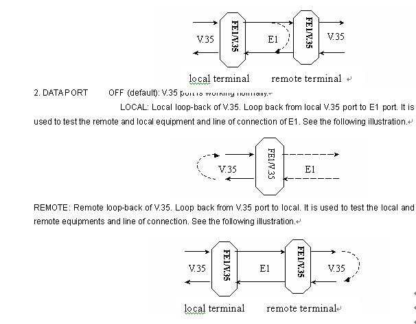
LOCAL: Local loop-back of E1. Loop back from local E1 port to V.35 port. It is used to test the local equipment and line of connection. See the following illustration.
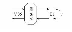
REMOTE: Remote loop-back of E1. Loop back from local E1 port to local. It is used to test the local equipment and line of connection of E1. See the following illustration.
Note: The command is used to realize E1 or V.35 remote loop-back. It is invalid unless it is send to the remote terminal by E1 lines. Therefore, the command is invalid in the following two cases. First, the remote equipment is not the Fractional E1/V.35 Interface converter. Second, the equipment is working in unframing state in which all time slots of E1 are used to transmit data of V.35 port in the speed of 2048Kbps.
TEST PARAMETER:
OFF (default): PRBS test is turned off.
ON: Pseudo-random test is turned on. The system will generate pseudo-random sequence sending to E1 output port and test whether inputting signals of E1 are consistent with the sequence. If the two are consistent, PTOK indicator will be on. Otherwise, it will be off.
Note: ① In any of the above test modes, the system will break off normal data communication services and transfer to test mode.
② In the process of pseudo-random test, a loop must be formed in the circuitry, or pseudo-random sequence sent out will be unable to return.
BERT PARAMETER:
1.FUNCTION OFF(default): disable BERT
ON:enable BERT function, transmit the produced serial of specified code type to E1 output port, sum up the receiving bits and error bits of E1 input signals and calculate error code rate.
2.PATTERN select the receiving/transmitting code type:
2E15-1(default)
2047
511
ALL 1
ALL 0
3.ERR INS SINGLE:insert a single error code.
4.RESULT Show the test result in different modes:
Er/Rx:0.0e-00(default)
SYNC/SYNCLOS
RX:0000000000
TX:0000000000
5.RESET Push the key ENTER, restart searching PATTERN, simultaneously reset the statistic BERT information.
6.RX INV DISABLE(default)
ENABLE:inverse the selection of PRS data at the receiving end of BERT.
7.TX INV DISABLE(default)
ENABLE:inverse the selection of PRS data at the transmitting end of BERT.
Operational procedure of BERT is as follows:
1、Pattern selection;
2、BERT enable, check the test result;
3、Change the Pattern as required;
4、Restart searching Pattern,simultaneously rest the statistic BERT information,then check the test result again;
5、Insert bit error as required, check the test result;
6、Inverse the PRS data at the receiving/transmitting end as required;
7、Restart searching Pattern,simultaneously rest the statistic BERT information,then check the test result again.
|